What is I2C?
I2C, or IIC as it is sometimes called, stands for Inter-Integrated Circuit and is a synchronous serial protocol which was developed to facilitate communication between micro-controllers and external peripherals (like sensors or external memory) using just two data wires.
Wiring
A typical I2C implementation requires two signal wires – SCL (Serial Clock) and SDA (Serial Data). No crossover connection is required, so you should connect the SCL of the master device to the SCL of the slave device – the same is true for the SDA connection.
The I2C pins are open-drain – this means the data pins are driven by a transistor, which will only pull the data lines to GND or it will leave the pin floating. As a result, the SCL/SDA pins will never be driven to +5v. This can lead to instability. To prevent this, you should connect pull-up resistors between the data lines and 5v. Resistors of at least 2kOhm will be sufficient. Fortunately, most Arduino boards will have these included already.
Additionally, like all communication protocols, a common ground must exist. Therefore, you should connect the GND pins of both the master and slave together!
Data Transmission
Bus Speed
Typically, the I2C bus will operate at a frequency of 100kHz, giving you a data transfer rate of 100kb/s. However, depending on the specific software and hardware configuration, it is possible to run the I2C bus at 3.4MHz, giving a data transfer rate of 3.4Mb/s. Typically the transfer rate for an Arduino will cap out at 400kHz (400kb/s).
Data Transactions
The I2C protocol for data transmission is well-defined. Each transaction will be made up of the following:
- Start Bit
- Address Bits (Typically 7 bits, sometimes 10)
- Read/Write Bit
- Response Bit
- Data Bits (x8), followed by a single response bit. These data bits along with the response bit will continue to be transacted until all the data has been sent.
- Stop Bit
Start Bit
When the master device wants to start communicating, a start signal needs to be sent. When this start condition is received, all the slave devices will become active and will start to listen for address bits.
Address Bits
The address bits identify the slave device that the data is for. For example, an MPU6050 has an address of 0x68. Therefore if the master wants to communicate with an MPU6050, it must write 0x68 to the bus. The 7 bits allow you to communicate with up to 127 different devices.
Read/Write Bit
The master needs to tell the slave whether it wants to write or read data from the device. This is indicated by the read/write bit.
Response Bit
On receipt of a valid address or data, the slave will send an acknowledge bit to the master. If the data is not properly received by the slave, then no acknowledgement bit will be sent, this indicates a bus/sensor error.
Data Bits
As mentioned above, 8 bits (one byte) will be sent. The perheprial will then respond with a response bit. Whilst there is data available, these data bits will continue to be sent by the master. Furthermore, the slave will continue to return the appropriate acknowledgement bit.
Stop Bit
When the master has done sending the data, it must send a stop bit to indicate the end of a data transaction.
I2C and the Wire Library
Fortunately, we do not have to develop an I2C implementation for ourselves. The developers over at Arduino produce an I2C library for us, they called in Wire.h.
Setting up Wire.h (Arduino I2C library)
- Import Wire.h, add “#include<Wire.h>” to the start of the sketch
- In void setup(), add the line “Wire.begin()”
Writing Data to a Perhiprial
- To begin a Write transaction, you need to begin a transmission. To do this, add the line “Wire.beginTransmission(DeviceAddress)”. The DeviceAddress variable must be the 8 bit address of the device. The Wire library will automatically alter the value provided to fit the required 7/10bit address.
- For every piece of data you want to write to the perheprial add the line “Wire.write(data)”, where the variable data is 8 bits in length.
- Once you have written all the data to the bus, you must end the transaction. To do this, add the line “Wire.endTransmission()”. This will send the stop bit to the bus, signalling the end of the I2C transaction.
Reading Data from a Perhiprial
- Begin an I2C read transaction. Add the line “Wire.requestFrom(DeviceAddress, NumberOfBytes)”. Where DeviceAddress is equal to the 8 bit address of the device.
- For every piece of data you want to read from the bus, add the line “Wire.read()”. This will return 1 byte of data sent by the perheprial. This code needs to be called until all the requested data is received.
Simple I2C bus Arduino Example
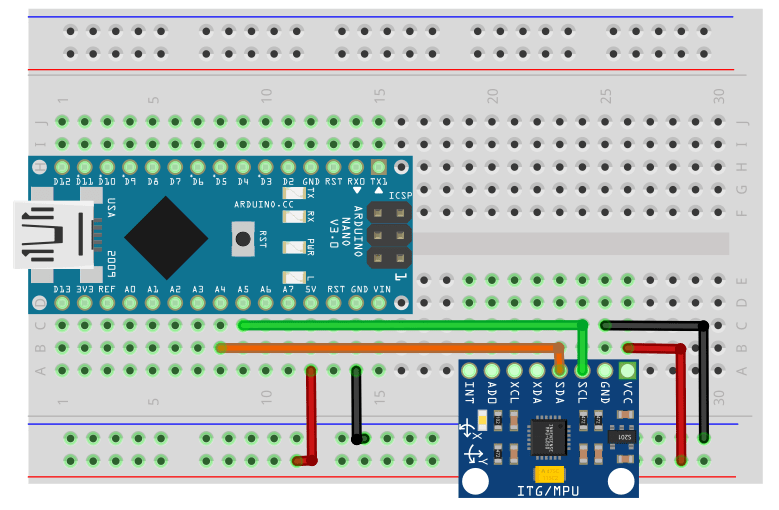
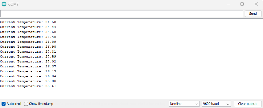
An MPU6050 is a combined accelerometer and gyroscope. One of the key parameters for this device is the current operating temperature. This example will show you how to read the current temperature of the device, using I2C.
Circuit Diagram

Code
#include <Wire.h>

void setup(){
    Serial.begin(9600);
    Wire.begin();

    /*
        Initialise the MPU6050
    */
    Wire.beginTransmission(0x68);// Begin the I2C transaction, device address 0x68
    Wire.write(0x6B);//Write the Register Address
    Wire.write(0x00);//Write the Data (0x00 in the register 0x00, activates the MPU6050)
    Wire.endTransmission();//End the data transaction
}
void loop(){
    Wire.beginTransmission(0x68); // Begin I2C transaction
    Wire.write(0x41);// Register to read the data from
    Wire.endTransmission();//End the write transaction

    Wire.requestFrom(0x68, 2);//Read 2 bytes from the MPU6050
    uint8_t temp_h = Wire.read();//Read the high byte
    uint8_t temp_l = Wire.read();//Read the low byte
    /*
        Calculate the raw tempterature
        Shift the high byte, 8 bits to the left
    */
    int16_t raw_temp = temp_h << 8 | temp_l;
    /*
        Convert the raw temperature into a "real" value
    */
    float temperature = (raw_temp/340.0)+36.53;
    Serial.print("Current Temperature: ");
    Serial.println(temperature);
    delay(1000);
}
I2C Bus Behaviour

In the image above, an analysis of the I2C bus has been conducted. The top line shows the SCL wire (Serial Clock) and the second line shows the SDA wire. Thirdly, the third line shows the data bits received on the I2C bus. Finally, the fourth line converts the individual bits transmitted, into human-readable data.
From left to right:
- Pink S – Signifies the start condition, firstly the write transaction
- Address Write: 68 – The address the Arduino is trying to write to. Device 0x68.
- Green A – The acknowledged bit
- Pink W – Signifies that this is a “write” transaction
- Data Write: 41 – The packet of data to be written to the bus. In this case, the starting register address
- Green A – The acknowledged bit
- Yellow P – Stop Condition
- Pink S – Signified the start condition – this time, the read transaction
- Address Read: 68 – The address the Arduino is trying to read from. Device 0x68.
- Green A – The acknowledged bit
- Data Read: F0. In this case the high byte of the device temperature data.
- Green A – The acknowledged bit
- Data Read: A0. In this case the high byte of the device temperature data.
- Green N – The “Not-acknowledge” bit, this signifies the device is done sending data
- Yellow P – Stop Condition
Serial Monitor Output

Conclusion
In this article, we have discussed what I2C is, how it works and how to implement reading and writing transactions using the Arduino Wire library.